UNINTERRUPTIBLE POWER SUPPLY (UPS)

Saturday, April 30, 2011

Uninterruptible Power Supply (UPS) is a power quality device, which provides continuous and conditioned power to a critical load. Also, the device averts power quality problems coming from the distribution system such as interruptions, voltage sags, swells, harmonics and noise from disrupting the performance of sensitive electronic components and other electrical equipment. In other words, a UPS provides protection against all types of interruption and, as a bonus, can also isolate the critical load from other power quality problems that are present in the incoming supply.

Moreover, the term uninterruptible power supply has been applied both to an uninterruptible power system and to the specific battery-inverter equipment. In this post, the term describes the specific equipment unless otherwise mentioned.
Uninterruptible Power Supply (UPS)
Applications and Operation 

Basically, an uninterruptible power supply can maintain power to critical equipment while the alternative source, like a standby generator set, is still brought online; or provides computers enough time to be properly shut off. In such circumstances, the UPS may only need to support the critical load for about 15 to 20 minutes. Nonetheless, it can also be considered to support the critical load for up to one hour. This depends on its design, which will require considerable extra energy storage capacity.

The uninterruptible power supply is widely used to maintain the safety and business critical systems located in computer rooms, process control stations, data centers, server areas and online processing (i.e. email, online banking and mobile phones). Therefore, end-users - especially commercial and industrial, are now able to fully maximize the availability of their systems and equipment and have the following benefits:

Ø  Computer jobs are not abruptly halted due to voltage sags and interruptions.
Ø  End-users are not hassled by computers and other devices shutting down.
Ø  Equipment does not incur the stress of another (hard) power cycle.
Ø  Avoid unnecessary critical data loss.

In addition, the uninterruptible power supply can be operated in parallel to provide added security of electrical power supply to the equipment connected to them. This is known as operating in “redundant configuration”, which means that if one module fails or is removed for maintenance, the other connected modules can support the critical load.

Uninterruptible Power Supply - Categories and Technologies

Uninterruptible Power Supplies can be categorized into two main sub-technologies:

1.    Static UPS
2.    Rotary UPS

Static Uninterruptible Power Supply (UPS)

Static Uninterruptible Power Supplies are designed and best suited for linear and constant loads. A static UPS, as the name suggest, has no moving parts unlike its rotary counterpart. It usually consists of three major components:

1.    Converter or rectifier

Converts the AC power into DC in order to charge the battery and power the inverter.

2.    An energy storage 

Typically, this is a battery which stores DC electrical energy.  The most common battery used by uninterruptible power supply manufacturers is the valve-regulated lead acid battery (VRLA). This is because the VRLA is self-contained, durable, relatively cheaper and environment-friendly.

3.    Inverter

The inverter converts back the stored DC into an AC voltage waveform that has been regulated and filtered for enhanced power quality.

Other components of the static UPS include:

Ø  Bypass or static switch (where required)
Ø  Electronic control system, which controls the operation of the product.
Ø  Power supply filter/s.

Static UPS Schematic Diagram
Moreover, static uninterruptible power supplies can be further classified into the following:

1.    Online UPS

Rotary Uninterruptible Power Supply (UPS)

The Rotary Uninterruptible Power Supply utilizes the inertia of a large, high-mass spinning flywheel to supply energy to the critical load in the event of interruptions. In addition, the flywheel serves as a barrier against voltage sags and surges. It is usually operated in conjunction with a motor-generator set, where the flywheel provides the back-up power only for the short period needed for the rotating systems to start up.

The rotary uninterruptible power supply is generally reserved for applications that require more than 100 kVA of protection (e.g. industrial applications). It is used where the system is large and the likelihood for short-circuits is high. This is because they are more durable and has the capability to handle such conditions better than the static uninterruptible power supply. In addition, a rotary UPS can handle non-linear and linear loads easily but are comparatively expensive.
Rotary Uninterruptible Power Supply Schematic Diagram
Moreover, modern UPS systems feature new technologies called hybrid systems. It uses a combination of static system, flywheels and motor-generator technologies to provide a robust and high power UPS system. These hybrid systems can be very efficient and provide high reliability.

However, in the end, it should be noted that the primary function of any uninterruptible power supply – whether static, rotary or the combination thereof, is to protect the power supply of electrical or electronic equipment when the power goes out. The electrical characteristics of the actual load being protected and external influences on the electrical system determine which technology is the best solution. Furthermore, other factors such as reliability, cost, and location/space should also be evaluated.

References:
Carbon Trust. (2010). Uninterruptible Power Supply. A guide to equipment eligible for Enhanced Capital Allowances. 
Kusko, A. and Thompson, M. (2007). Power Quality in Electrical Systems. New York: McGraw-Hill.

ELECTRONIC VOLTAGE REGULATOR (EVR) FOR LOW VOLTAGE POWER QUALITY APPLICATIONS

Wednesday, April 27, 2011

Electronic Voltage Regulator (EVR) is a type of automatic voltage regulator that is typically used in low voltage power quality applications. It is a single-phase power quality device that functions to protect equipment from overvoltage and undervoltage. The electronic voltage regulator’s performance and speed make it appropriate for commercial and industrial power quality applications than the mechanical voltage regulator. In addition, EVRs come in two types: Tap Switching and Double Conversion.
Electronic Voltage Regulator (EVR)
Electronic Tap Switching Voltage Regulator

An electronic tap switching voltage regulator operates in the same principle as the mechanical tap changing regulator (i.e. step-voltage regulator). However, this type of electronic voltage regulator utilizes solid-state semiconductor switches such as the silicon controlled rectifier (SCR) and the triac for tap-changing, rather than the mechanical servo drives and brushes. The use of semiconductor switches makes the EVR regulate voltage much faster than the mechanical AVR. Also, electronic tap switching voltage regulators are either full power semiconductor (FPS) or the series transformer (ST) type.

Full power semiconductor type of electronic tap switching voltage regulator is the most common type of electronic voltage regulator. Generally, all but one of the SCR or triac switches are OFF. This design guides the current to flow only through the desired tap. If the embedded controller detects the need for a tap change, it will deactivate the semiconductor switch on one tap and turns ON the triac or SCR for the required tap. However, in this setup the solid-state switches are prone to damage caused by overload, inrush, or short circuit currents.
Electronic Voltage Regulator - Full Power Semiconductor
On the other hand, the series transformer type of electronic tap switching voltage regulator eliminates the weakness of the solid-state semiconductor switch against high currents. Its design employs additional transformer components to isolate the triacs or SCRs from the path of the load current. Consequently, this provides the electronic voltage regulator with the simplicity and speed of the FPS type and the high tolerance to excessive currents of the mechanical voltage regulator.
Electronic Voltage Regulator - Series Transformer Type

Double Conversion Electronic Voltage Regulator

Unlike the tap switching EVR, the double conversion electronic voltage regulator uses a rectifier to convert AC power to DC and then uses an inverter to convert the DC power back to AC - hence, the name double conversion.

In this type, there are two ways to regulate the output voltage:

1.    Regulating the DC voltage output from the rectifier
Ø     Least cost of components

2.    Supplying a constant DC voltage to the inverter
Ø     This includes adjusting the voltage level during the conversion back to AC in the inverter. Also, this is the usual method used by an uninterruptible power supply (UPS).

Reference:
Utility Systems Technologies, Inc. (2009). AC Automatic Voltage Regulators

BASIC STEPS IN SOLVING POWER QUALITY PROBLEMS

Monday, April 25, 2011

Steps in solving power quality problems usually include interaction between the utility supply system and the customer facility. This is because power quality problems have different causes that can be traced from both the utility and the end-users. Consequently, different solutions are available in order to improve the power quality and equipment performance. The problem solving process should also consider whether the assessment involves an existing power quality problem or one that could result from a new design or from proposed alterations to the system.

The basic steps in solving power quality problems involve the following:
Steps in Solving Power Quality Problems
Steps in Solving Power Quality Problems (Courtesy of Electrical Power Systems Quality)

1.     Identify the power quality problem

This is very important since this will be the basis for the solutions to be considered. Knowledge of the different power quality problems will surely come in handy (i.e. voltage sag/swell, interruptions, harmonics, etc.).

2.     Power Quality Problem Characterization

This step in solving power quality problems includes data gathering and measurements. Measurement is the primary method of characterizing the problem or the existing system that is being evaluated. In addition, it is essential to record impacts of the power quality variations at the same time when carrying out the measurements - so that problems can be easily correlated with the possible causes. Power Quality Analyzers and Meters play a vital role in this part.

3.     Identify and propose solutions to the PQ problem

Power quality solutions are identified at all levels of the system from the utility (transmission and distribution level) down to the end-user equipment being affected. This step shall include looking at equipment ride-through capability and power quality mitigating devices.

4.     Evaluate the proposed solutions

Proposed solutions are then evaluated based on both the technical and economic aspects. Limitations are also considered in this step. Power quality problem solutions are first evaluated and screened technically to determine their feasibility. Then, only the remaining viable alternatives are compared on an economic basis.

5.     Optimal Solution

Basically, the solution/s that can solve the power quality problem/s present in the facility with the least cost is the optimal solution. In short, it is the most cost-effective alternative. It will depend on the number of end-users being affected, type of power quality problem and the possible solutions.

Reference:
Dugan, R., McGranaghan, M., Santoso, S., and Beaty, H.W. (2004). Electrical Power Systems Quality (2nd ed.). New York: McGraw-Hill

AMBIGUOUS POWER QUALITY TERMS

Sunday, April 24, 2011

Ambiguous Power Quality Terms have proliferated in the power quality community today. Generally, these confusing terms are created by marketers, using many colorful phrases to attract and entice potential customers to buy their products. Unfortunately, many of these terms can’t be used for technical definitions. As a result, the Institute of Electrical and Electronics Engineers (IEEE) has discouraged the use of ambiguous terms in order to avoid and prevent confusion.

An example is “brownout”, which was mentioned in the Undervoltage post of this site. Brownout is sometimes used to describe sustained periods of low power frequency voltage initiated as a specific utility dispatch strategy to reduce delivered power. The power quality problem described by brownout has the same meaning as that of undervoltage. Yet, there is no formal definition for brownout and it is not as clear as the term undervoltage.

Therefore, the ambiguous power quality terms are meaningless in terms of describing an event and determining a solution. Here is a list of such terms:

Ø      Blackout
Ø      Brownout
Ø      Outage
Ø      Bump
Ø      Glitch
Ø      Blink
Ø      Power surge
Ø      Clean ground
Ø      Raw power
Ø      Clean power
Ø      Spike
Ø      Dirty ground
Ø      Dirty power
Ø      Wink

The unqualified use of these ambiguous power quality terms for describing power quality phenomena is discouraged. Use the standard terms as much as possible or qualify nonstandard terms with proper explanation.

Reference:
Dugan, R., McGranaghan, M., Santoso, S., and Beaty, H.W. (2004). Electrical Power Systems Quality (2nd ed.). New York: McGraw-Hill

POWER QUALITY BASICS: INTERRUPTIONS

Saturday, April 23, 2011

Interruptions are classified by IEEE 1159 into either a short-duration or long-duration variation. However, the term “interruption” is often used to refer to short-duration interruption, while the latter is preceded by the word “sustained” to indicate a long-duration. They are measured and described by their duration since the voltage magnitude is always less than 10% of nominal.

It is one of the general categories of power quality problems mentioned in the second post of the power quality basics series of this site.

Interruption
Interruption
Interruption is the power quality problem with the most perceivable effect on facilities. It generally affects the industrial sector, particularly the continuous process industry. In addition, the communication and information processing business is also significantly disturbed.

Short-duration Interruption

Interruption is defined as the decrease in the voltage supply level to less than 10% of nominal for up to one (1) minute duration. They are further subdivided into: Instantaneous (1/2 to 30 cycles), Momentary (30 cycles to 3 seconds) and Temporary (3 seconds to 1 minute).

Interruptions mostly result from reclosing circuit breakers or reclosers attempting to clear non-permanent faults, first opening and then reclosing after a short time delay. The devices are usually on the distribution system, but at some locations, momentary interruptions also occur for faults on the subtransmission system. The extent of interruption will depend on the reclosing capability of the protective device. For example, instantaneous reclosing will limit the interruption caused by a temporary fault to less than 30 cycles. On the other hand, time delayed reclosing of the protective device may cause a momentary or temporary interruption.

Aside from system faults, interruptions can also be due to control malfunctions and equipment failures.

Consequences of short interruptions are similar to the effects of voltage sags. Interruptions may cause the following (but not limited to):

Ø  Stoppage of sensitive equipment (i.e. computers, PLC, ASD) 
Ø  Unnecessary tripping of protective devices
Ø  Loss of data
Ø  Malfunction of data processing equipment.

Sustained Interruption

Sustained Interruption is defined by IEEE 1159 as the decrease in the voltage supply level to zero for more than one (1) minute. It is classified as a long duration voltage variation phenomena. Sustained interruptions are often permanent in nature and require manual intervention for restoration. In addition, they are specific power system phenomena and have no relation to the usage of the term outage. Outage does not refer to a specific phenomenon, but rather to the state of a system component that has failed to function. Furthermore, in the context of power quality monitoring, interruption has no relation to reliability or other continuity of service statistics.

Sustained interruptions are usually caused by permanent faults due to storms, trees striking lines or poles, utility or customer equipment failure in the power system or miscoordination of protection devices. Consequently, such disturbances would result to a complete shutdown of the customer facility.

Interruptions and Voltage Sags

Some interruptions may be preceded by a voltage sag,particularly when these PQ problems are due to faults on the source system. The voltage sag occurs between the time a fault initiates and the protective device operates. On the faulted feeder, loads will experience a voltage sag followed immediately by an interruption. The figure below illustrates a momentary interruption during which voltage on one phase sags to about 20 percent for about 3 cycles, which subsequently drops to zero for about 1.8 s until the recloser closes back in.

Interruption after a Voltage Sag
Interruption after a Voltage Sag (Courtesy of Electrical Power Systems Quality)
Also, as mentioned, the effects of voltage sags are almost similar to interruptions. Yet, interruptions affect the majority of end-users, while voltage sags only impact the more sensitive end-users. In other words, if other customers on the same circuit are also affected, then, the probability is high that the disturbance is due to interruption and not voltage sag.

Interruption - Prevention and Protection

To prevent interruptions, the utility may do the following:

1.    Reduce incidents of system faults
Ø  Includes arrester installation, feeder inspections, tree trimming and animal guards

2.    Limit the number of affected customers interrupted
Ø  Improve selectivity through single-phase reclosers and/or extra downstream reclosers

3.    Fast reclosing

To protect equipment from interruptions, end-users may use Uninterruptible Power Supply (UPS) and other energy storage systems. Back-up generator or Self-generation is necessary for sustained interruptions. Other solutions include the use of static transfer switch and dynamic voltage restorer with energy storage.


Synopsis:

Magnitude:
Short Interruption - Less than 0.10 per unit
Sustained interruption – 0.0 pu 

Duration:
Short Interruption - ½ cycle to 1 minute
Sustained interruption - More than 1 minute

Source: Utility or facility
Symptoms: Equipment Shutdown
Occurrence: Less than 2 interruptions/year in the US
Protection: Uninterruptible Power Supply (UPS)Self-generation, Energy storage  

References:

Dugan, R., McGranaghan, M., Santoso, S., and Beaty, H.W. (2004). Electrical Power Systems Quality (2nd ed.). New York: McGraw-Hill.
IEEE 1159-1995. Recommended Practice For Monitoring Electric Power Quality. New York: IEEE, Inc.
Short, T. (2006). Distribution Reliability and Power Quality. Boca Raton: CRC Press
Utility Systems Technologies, Inc. (2009). Power Quality Basics

STEP-VOLTAGE REGULATORS IN THE UTILITY DISTRIBUTION SYSTEMS

Thursday, April 21, 2011

Step-Voltage Regulators applied in the utility’s distribution systems are generally medium-voltage mechanical automatic voltage regulators (AVR). It should be noted that there are two distinct types of AC automatic voltage regulators: Medium-voltage (mechanical) and the Low-voltage regulators (mechanical or electronic). The difference in their operation and design clearly demonstrate that their applications are not the same. The latter is intended to protect end-user devices from overvoltage and undervoltage conditions . Nonetheless, this post will focus on the medium-voltage regulators, which is primarily used by the electric utility to compensate for the voltage drop in the feeders or distribution systems. In addition, the term step-voltage regulator is often used to refer to utility AVR.

Step-Voltage Regulators - Utility Applications
Step-Voltage Regulators for Utility Applications (Courtesy of Electrical Power Systems Quality)

Step-Voltage Regulator Basic Operation

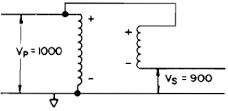
The step-voltage regulator is basically a transformer that has its high-voltage winding (shunt) and low-voltage winding (series) connected to either aid or oppose their respective voltages. Subsequently, the output voltage could be the sum or difference between the winding voltages. For example, if the transformer has a turns ratio of 10:1 with 1000 V applied in the primary, then, the secondary voltage will be 100 V. Adding or subtracting by using the connection mentioned above - the output voltage would be 1100 V or 900 V, respectively. Thus, the transformer becomes an autotransformer with the capability to boost (raise/step-up) or buck (lower/step-down) the system voltage by 10%.
Voltage Regulator (Boost)
Step-up Autotransformer (Boost)
Voltage Regulator (Buck)
Step-down Autotransformer (Buck)
In other words, by switching the location of the physical connection from the shunt to the series winding (reversing switch) and with the turns ratio made variable through automatic tap-changing - the system voltage is adjusted to the required level. This is made possible since the automatic voltage regulator includes microprocessor-based and/or mechanical controls that tell the unit when and how to change taps. Moreover, modern controllers are equipped with data acquisition and communication capabilities for remote applications.
Step Voltage Regulator Schematic Diagram
Utility step-voltage regulators usually allow a maximum voltage regulation range of ±10% of the incoming line voltage in 32 steps of 5/8% or 0.625%. That makes 16 steps each for buck and boost – 5/8% x 16 steps = 10%. Utility AVRs can be installed out on the feeders or at the substation bus. The voltage regulator units could either be single-phase or three-phase. However, on a three-phase feeder, it is more common in utility applications to use single-phase units connected in banks of three (e.g. wye-grounded, closed delta). This is because utility distribution lines are typically unbalanced in their construction, added with single-phase loads that create significant unbalance in the line currents. Thus, three independently controlled regulators may very well yield better balance between the phase voltages than a single three-phase unit or ganged operation. Also, there are many installations of open-delta regulator banks on lightly loaded three-phase feeders, which require only two regulators and are less costly than a full three-phase bank.

Voltage Regulator Grounded Wye Connection
Voltage Regulator Grounded Wye Connection 
Voltage Regulator Open-Delta Connection
Voltage Regulator Open-Delta Connection 

Voltage Regulator Applications

Step-voltage regulators are typically installed on the following:

Ø   Existing feeders - before the point where the voltage drop problem starts with heavy load 
Ø   Important laterals
Ø  To serve a remotely located load

Voltage regulators in the utility distribution systems are relatively slow. These AVRs have a time delay of at least 15 seconds. Therefore, it is not suitable to applications where voltages may vary in cycles or seconds.  Utility step-voltage regulators are primarily use for boosting voltage on long feeders where the load is changing slowly over several minutes or hours. The voltage band typically ranges from 1.5 to 3.0 V on a 120-volt base. The control can be set to maintain voltage at some point down the line from the feeder by using the line drop compensator capability. This results in a more level average voltage response and helps prevent overvoltages on customers near the regulator.

Voltage Regulator Sizing and Connection

These are the basic steps in determining the size and connection type of the voltage regulator for utility applications:

1.   Determine the system configuration (i.e. 3-phase, 4-wire multigrounded wye or 3-phase, 3-wire delta). This will be the basis for AVR connection type.
2.     Establish the amount of voltage regulation needed (e.g. ±5%, ±10%)
3.   Determine the system phase voltage on which the AVRs will be connected. Remember that the phase voltage is affected by the system configuration (1).
4.     Calculate the maximum load current of the feeder or line.
5.     Multiply the voltage regulation (2), system phase voltage (3) and maximum line current (4) to get the required kVA size of the automatic voltage regulator.

For example, compute for the step-voltage regulator size needed by a 3-phase, 4-wire multigrounded feeder with a system voltage of 13800Y/7970 V. The required voltage regulation is 10% and the peak connected load is 6.0 MVA.

1.    System Configuration is 3-phase, 4-wire, multigrounded wye - means that the voltage regulators shall be connected grounded wye.
2.     Voltage regulation = 10%
3.   Phase voltage is the line-to-neutral voltage = 7.97 kV (since it is a 4-wire multigrounded wye feeder)
4.     Load current = 6.0 MVA / (1.732 x 13.8 kV) = 251 A
5.     Voltage Regulator kVA Size = 10% x 7.97 kV x 251 A = 200 kVA

Use three 32-step voltage regulators, each with a standard rating of 250 kVA, 7970 V, ±10% regulation.

For a more detailed explanation about step-voltage regulators (Click here)

References:
Cooper Power Systems. (1993). How Step-Voltage Regulators Operate. Pittsburgh: Cooper
Dugan, R., McGranaghan, M., Santoso, S. and Beaty, H.W. (2004). Electrical Power Systems Quality (2nd ed.). New York: McGraw-Hill.
Utility Systems Technologies, Inc. (2009). Comparison of Automatic Voltage Regulators for Utility Versus Power Quality Applications. New York: UST, Inc.

PQWorld

free counters

About Me

My photo
I am a Professional Electrical Engineer with a Masters Degree in Business Administration. My interest is in Power Quality, Diagnostic Testing and Protective Relaying. I have been working in an electric distribution utility for more than a decade. I handle PQ studies, power system analysis, diagnostic testing, protective relaying and capital budgeting for company projects.