UPS SIZING: RECTIFIER AND INVERTER

Monday, May 30, 2011

The sizing of the Rectifier and Inverter follows once the overall UPS size has been determined. Most of the time, the suppliers will only ask the UPS VA rating and they will do the rest. However, as an engineer, knowing how to determine the corresponding rectifier and inverter size will help you evaluate the practicality of the specifications given by the supplier. For that reason, this post includes the sizing calculations with an example for easy learning.


Rectifier or Charger

The rectifier should be properly sized to satisfactorily perform these two tasks:  Supply the inverter at full load (Ir) and charge the batteries at the maximum charge current (Ic). Therefore, the rectifier DC load current (Idc) is the sum of Ir and Ic. In equation form: Idc = Ir + Ic

The design DC load current is the current drawn by the inverter from the rectifier at full load.

Ir = S/Vdc

where:

Ir = Design DC full load current (A)
S = UPS VA rating
Vdc = nominal battery / DC link voltage

Since a 1000 VA UPS was selected, then,

Ir = 1000 VA / 120 V = 8.33 A.

Meanwhile, the maximum battery charging current can be computed as follows:

Ic = (C X f)/t

where:

Ic = maximum DC charge current (A)
C = selected battery capacity (Ampere-hour or Ah)
f = battery recharge efficiency (typically 1.1)
t = minimum battery recharge time (hours)

In the example, for a 60 Ah battery as calculated in UPS Sizing: Battery Capacity, and recharge time of 2.25 hours,

Ic = (60 Ah X 1.1) / 2.25
Ic = 29.33 A

Thus, the total minimum DC rectifier/charger current is:

Idc = 8.33 + 29.33 = 37.7 A

Select the next standard rectifier rating that exceeds the total minimum DC current above.

Use a 40-Ampere Rectifier.

Inverter Sizing

The inverter must be rated to continuously supply the UPS loads. Therefore, the inverter shall be sized based on the selected UPS VA rating.

For a three-phase UPS:
Iac = S / (1.732 X Vo)

For a single-phase UPS:
Iac = S/Vo

where:

Iac = design AC full load current (A)
S = UPS VA rating
Vo = nominal AC output voltage (line-to-line voltage for a three phase UPS)

As an example, a single-phase 1000 VA UPS shall have an inverter size of:

Iac = 1000 VA / 120 V
Iac = 8.33 A

Select the next standard inverter rating that exceeds the design AC load current.

Use a 10-Ampere Inverter.

UPS SIZING: BATTERY CAPACITY

Battery Sizing guarantees that loads being supplied are adequately served for its designed autonomy time. Improper capacity sizing could jeopardize batteries used in applications such as Uninterruptible Power Supply (UPS), solar power systems, emergency lighting and telecommunications.

The calculations done on this post were based on the ampere-hour method for sizing battery capacity with reference to IEEE 485 and IEEE 1115. Also, it focuses only on lead-acid and nickel-cadmium (NiCd), which are two of the most common battery types used for UPS applications.
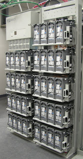

UPS Battery
UPS Battery Bank
The Battery Sizing involves these steps:

1. Identify the Battery Loads

Just like in UPS Sizing, the first step is to identify and select the loads that the battery will be supporting. This is dependent to the application of the battery, such as UPS systems. In this case, the battery load will be the same as that selected for the UPS.

2. Create the Load Profile

Refer to the UPS Sizing: Load Profile post for details on how to create a load profile and subsequently derive the design load and energy demand. IEEE refers to the load profile as the duty cycle. The resulting design energy demand in the example is 4020 VAh. 

3. Select the Battery Type

IEEE suggested that the following factors should be considered in selecting the battery type:

Ø  Application design life and expected life of cell
Ø  Physical characteristics (dimensions, weight)
Ø  Ambient temperature
Ø  Charging characteristics
Ø  Frequency and depth of discharge
Ø  Ventilation requirements
Ø  Maintenance requirements
Ø  Seismic factors (shock and vibration)
Ø  Cell orientation requirements

Subsequently, find the characteristics of the battery cells (generally from supplier data sheets), which includes the following:

Ø  Battery cell capacities in Ampere-hour (Ah)
Ø  Cell temperature
Ø  Electrolyte density at full charge (for lead-acid batteries)
Ø  Cell float voltage
Ø  Cell end-of-discharge voltage (EODV)

For the example, the selected battery type is the valve-regulated lead acid (VRLA) battery.

4. Number of Cells in Series

The number of cells in a battery is computed to match the minimum and maximum voltage tolerances of the load. As a minimum, the battery at its EODV must be within the minimum voltage range of the load. Meanwhile, as a maximum, the battery at float voltage (or boost voltage) needs to be within the maximum voltage range of the load. The cell charging voltage depends on the type of charge cycle that is being used, e.g. float, boost, equalizing, etc, and the maximum value should be chosen.

The number of battery cells required to be connected in series must fall between the two following limits:

Nmin = Vdc*(1+Vmax) / Vc
Nmax = Vdc*(1-Vmin) / Veod

where:

Nmin = minimum number of battery cells
Nmax = maximum number of battery cells
Vdc = nominal battery voltage (V)
Vmin = minimum load voltage tolerance (%)
Vmax = maximum load voltage tolerance (%)
Veod = cell end of discharge voltage (V)
Vc = cell charging voltage (V)

As an example, the minimum and maximum load voltage tolerances are Vmin = 10% and Vmax = 10%, respectively. For the battery, nominal voltage is Vdc = 120V, end-of-discharge voltage is Veod = 1.8V/cell, and the cell charging voltage is Vc = 2.05V/cell. Then,

Nmax = 120(1+0.1) / 2.05
Nmax = 64.4 or 64 cells

Nmin = 120(1-0.1) / 1.8
Nmin = 60 cells

Use 62 cells in series (number of cells between 60 and 64).

5. Determine Battery Capacity

Other than the energy demand and battery nominal voltage, several other factors may affect the computation for battery capacity. These factors are discussed below:

Aging Factor (ka)

Battery performance decreases with increase in age. To ensure that the battery can meet capacity throughout its useful life, an aging factor is applied - generally 1.25. There are some exceptions - consult the supplier.

Temperature Correction Factor (kt)

Batteries are specified by a standard operating temperature of 25°C, a deviation from this value should be taken into account by applying a correction factor. The values can be gathered from the manufacturer. However, high temperatures reduce battery life irrespective of capacity and the correction factor is for capacity sizing only. Meaning, battery life can’t be increased by increasing capacity.

Capacity Rating Factor (kc)

This accounts for voltage depressions during battery discharge. IEEE 1115 Annex C suggests that for float charging applications, Kt = rated capacity in Ah / discharge current in Amps (for specified discharge time and EODV).

Taking the abovementioned factors into consideration, the minimum battery capacity required to carry the design load over the specified autonomy time shall be calculated as follows:

B = [Energy demand X (ka X kt  X kc)] / (Vdc X kd)

where:

B = required battery size or capacity
ka = aging factor (%)
kt = temperature correction factor (%)
kc = capacity rating factor (%)
kd = depth of discharge (%)
Vdc = nominal battery voltage (V)

Select the next standard rating that exceeds the minimum Ah battery capacity.

For example, compute for the minimum battery capacity using the given energy demand of 4020 VAh from UPS Sizing: Load Profile, battery aging factor (ka) = 25%, temperature correction factor at 30 deg C (kt) = 0.956, capacity rating factor (kc) = 10% and depth of discharge (kd) = 80%.

B = [4020 VAh X (1.25 X 0.956 X 1.1)] / (120 V X 0.8)
B = 55.04 Ah

Use a VRLA battery with a 60 Ah capacity.

References:
IEEE 485-2003. Recommended Practice for Sizing Lead-Acid Batteries for Stationary Applications
IEEE 1115-2005. Recommended Practice for Sizing Nickel-Cadmium Batteries for Stationary Applications

UPS SIZING: LOAD PROFILE

The Load Profile is basically a graph showing how the load demand changes with respect to time. It is the subsequent step after choosing the critical and essential loads for uninterrupted power protection. Through the load profile, the design load and energy demand values, which are prerequisites for UPS Sizing calculation, can be derived.

CLICK HERE TO GO TO UPS SIZING MAIN PAGE

There are two techniques for creating a load profile:

1.  Autonomy Method

This is the conventional way used for emergency and backup power applications, such as in UPS systems. The instantaneous loads are displayed over a so-called autonomy time, which is the period of time that the loads need to be supported by a backup power system in the event of an interruption. IEEE 446 has published typical autonomy times for some of the critical and essential devices.

2. 24-Hour Profile

This method is more commonly associated with stand-alone applications, like in solar power systems. It displays the average instantaneous loads over a 24-hour period.

However, this post will only focus on the autonomy method in order to make a load profile for UPS Sizing.

Basic Steps

Preparation of Load List

1.      List all the selected critical and essential equipment to be protected by the UPS in one column.
2.      Read the nameplate of each load and write down the voltage (V) and current (A).
3.      Multiply the voltage and current in order to get the Volt-Ampere (VA) or apparent power for each load and enter these values in another column. Sometimes, the nameplate will only indicate the real power or load in Watts. In this case, divide the wattage by its nameplate power factor (PF) to derive the load VA. If PF is unknown, use typical values of 0.6 to 0.7.
4.     Decide on the autonomy time for each equipment. Some loads may only be required to ride through short interruptions or to have enough time for proper shut down. Meanwhile, other critical equipment may need to operate for as long as possible.
5.      Multiply the load VA and Autonomy time for each load and write the results (VAh) in the last column.
6.      Get the total for VA and VAh.

UPS Sizing Load List
Sample Load List for the Critical and Essential Equipment
Graph the Load Profile

Using the autonomy method, the load profile is constructed by piling the energy or VAh rectangles on top of each other. An energy rectangle has the autonomy time as its width and the load VA as height. The load profile is created by piling the widest rectangles first (i.e. equipment with the largest autonomy time).

UPS Sizing Load Profile
Load Profile for the Selected Loads
Design Load and Energy Demand

Prior to the calculation of the design load and energy demand, there is a prerequisite to set the design margin factor (DMF) and the load growth factor (LGF).

The design margin factor is used to account for any inaccuracies in estimating the load that may lead to UPS overloading. A 1.25 factor is usually recommended. On the other hand, the future load growth factor is typically in the range between 1.1 to 1.3. If certain that no future loads are expected, then this allowance can be omitted (not advisable).

Design Load

It is the total load VA of all the critical and essential equipment that should be protected from interruptions. This value is the basis for the UPS size, as well as for the inverter and rectifier.

Design Load = Total Load VA X (DMF) X (LGF)

Design Energy Demand

Computing for the energy demand is important for the sizing of energy storage devices such UPS batteries. It is calculated by finding the area under the load profile curve, which in this case is the total area of the rectangles. In other words, the energy demand is simply the total VAh of the loads multiplied by the margin and load growth factors.

Design Energy Demand = Total Load VAh X (DMF) X (LGF)

Example:

The total peak load apparent power is 640 VA and the total load energy is 2680 VAh. Using a margin factor of 1.25 and 1.2 growth factor, the following are calculated:

Design Load = 640 VA X (1.25) X (1.2)
Design Load = 960 VA

Design Energy Demand = 2680 VAh X (1.25) X (1.2)
Design Energy Demand = 4020 VAh


Reference:
IEEE 446-1995. Recommended Practice for Emergency and Standby Power Systems for Industrial and Commercial Applications

UPS SIZING: GUIDE FOR UNINTERRUPTED POWER

Sunday, May 29, 2011

UPS Sizing is an important process in order to closely match the UPS capacity to its load. This is done to come up with a sufficient overall uninterruptible power supply, so that it will operate efficiently at the lowest possible cost. An oversized UPS system will lead to increased operating expenses, while an undersized unit will be susceptible to overloading and has a small load capability for long-term growth. Also, UPS sizing aims to determine the practical ratings of its main components – battery, rectifier and the inverter. 

The UPS Sizing process involves the following five basic steps:

1.    Identify and select the prospective UPS loads
2.    Create a load profile and derive the UPS design load (VA) and energy (VAh)
3.    Compute the battery size (number of cells in series and Ah capacity)
4.    Determine the overall UPS Size
5.    Determine the size of the UPS rectifier and inverter

The following discussions include the details for each basic step in UPS sizing plus an example in order to guide through the entire process.

Identify and Select the UPS Loads

In UPS Sizing, the first step is to identify and select the critical and essential equipment that need to be protected from the damaging effects of voltage sags and interruptions. Listed below are some of the possible loads, which may require uninterruptible power supply.

Critical Loads: Data Center, DCS and ESD processor, telecommunications equipment, blade file servers and other sensitive electronics.

Essential Loads: Lighting, Heating and Ventilation.

As an example, the following loads are chosen for UPS protection: Telecommunications, Computer Console, DCS cabinet and ESD cabinet.

Create the Load Profile

Refer to the UPS Sizing: Load Profile post for details on how to create a load profile and subsequently derive the design load and energy demand. The resulting load profile, design load VA and energy demand VAh of the selected equipment are shown below:

UPS Sizing Load List
Sample Load List 
Design Load: 960 VA
Design Energy Demand: 4020 VAh

Battery Capacity 

Refer to the  UPS Sizing: Battery Capacity post for details on how to size the battery for UPS applications. Meanwhile, additional information regarding battery sizing for UPS applications are discussed below:

Nominal Battery or DC Link Voltage

This is often selected by the UPS supplier. However, if required to be selected, the following factors should be considered:

·         DC output voltage range of the rectifier – the rectifier must be able to output the specified DC link voltage
·    DC input voltage range of the inverter – the DC link voltage must be within the input voltage tolerances of the inverter. Note that the battery end of discharge voltage should be within these tolerances.
·        Total DC link current at full load – affects the sizing of DC cables and inter-cell battery links.
·       Number of battery cells required in series – this will affect the overall dimensions and size of the battery rack. If physical space is a constraint, then fewer batteries in series would be preferable.

In general, the DC link voltage is usually selected to be close to the nominal output voltage.

Overall UPS Sizing

The overall UPS Size is to be based on the computed design load VA from the load profile. The idea is to simply select the next standard UPS rating that exceeds the design load VA.

Design load = 960 VA
Use a 1000 VA UPS (Next standard UPS rating)

Rectifier and Inverter Sizing

Refer to the UPS Sizing: Rectifier and Inverter post for details on how to size the corresponding rectifier and inverter. In the example, for a selected UPS rating of 1000 VA and battery capacity of 60 Ah, the sizes are:

Rectifier

Idc = 37.7 A; Use a 40-Ampere DC rectifier.

Inverter Size (Single-phase Inverter and 120 V output)

Iac = 8.33 A; Use a 10-Ampere Inverter.

Reference:
IEEE 446-1995. Recommended Practice for Emergency and Standby Power Systems for Industrial and Commercial Applications

SURGE ARRESTER SELECTION GUIDE

Thursday, May 26, 2011

In this Surge Arrester Selection Guide, an overview of the processes and criteria are given. This post is not intended to be an all encompassing reference but only as a review of the basic steps necessary to choose the appropriate surge arrester for a particular application.  In addition, a detailed input from other sources such as the manufacturer should be obtained.

The main objectives of this surge arrester guide are:

Ø    To select the lowest rated surge arrester that will give sufficient equipment insulation protection
Ø   To determine the ratings of the surge arrester such that it will have an acceptable service life when connected to the electric power system.

An arrester of the minimum practical rating is preferred since it provides the highest margin of protection for the equipment insulation system. It should be noted that there is a thin line between service life and protection of a surge arrester. Higher ratings tend to increase its capability to survive on a certain power system. However, this reduces the protective margin it provides for a specific insulation level. Thus, the engineer should properly consider both surge arrester survival and equipment protection in the specification and selection process.

The appropriate selection and application of surge arresters in a system involve the following decisions: Arrester Type and Ratings, Physical Location and Insulation Coordination.

Arrester Types and Ratings

Arrester Class and Types

The surge arrester types are basically based on the main conductive elements:

  • Expulsion Type
  • Silicon Carbide (SiC)
  • Metal Oxide Varistors (MOV)

According to IEEE, there are four classes of surge arresters. In order of protection, capability and cost, the classes are:

  • Station
  • Intermediate
  • Distribution
  • Secondary
Station Class Surge Arrester
Arrester Ratings

  • Duty Cycle
  • Maximum Continuous Operating Voltage (MCOV)
  • Temporary Overvoltage (TOV)
  • Maximum Discharge (ANSI) or Residual (IEC) Voltage
  • Pressure Relief / Short-Circuit Capability
  • Energy Absorption

Arrester Location

NEC Article 280 mentioned that the conductors for the surge arresters should not be longer than necessary, and unnecessary bends should be avoided. In connection, there is a need to assess the physical location of the surge arrester, which affects its lead length, as well as the voltage increase due to separation distance effect.

Insulation Coordination

The degree of insulation coordination is determined by the magnitude of three protective margins. The protective ratios must be met or exceeded if satisfactory insulation coordination is to be achieved, according to the minimum recommendations given in ANSI C62.22.

Ø  Equipment Front-of-Wave Protective Margin
Ø  Impulse Margin of Protection
Ø  Switching Surge Protective Design

References:

Hernandez, J. Lightning Arresters: A Guide to Selection and Application
IEEE Tutorial on Surge Protection in Power Systems
Pryor, L. The Application and Selection of Lightning Arresters

ETAP TUTORIALS: COMPOSITE NETWORKS

Sunday, May 22, 2011

This ETAP Tutorial presents the Composite Networks feature, which is one of ETAP’s most useful modelling tools. When building a one-line diagram of very large and complicated systems, the model becomes prone to criss-crossing lines and may look disorganized and messy. However, using the composite networks, such problems will be reduced or eliminated. The importance of this feature is due to the fact that it enhances the one-line diagram, which is the backbone of power system simulations including power quality studies.

A composite network is a combination of all components in a subsystem, because it can also contain buses, sources, loads, branches and even other composite networks or composite motors. The number of levels where you can nest composite networks inside of other composite networks is unlimited. This allows the engineer to create systems and nest elements by their physical layout, geometrical requirements of elements, voltage levels, study requirements, etc. Subsequently, composite networks offer the capability to build complicated electrical networks while still maintaining a clean and organized one-line diagram. As a result, the user can display the system that he wants to emphasize, while the next level of system detail is within easy reach.

Furthermore, these nested composite networks are still part of the over-all system model. All studies that are run take in all the elements and connections nested within all composite networks and composite motors.

At the end of this tutorial, one should be able to create large and complex systems in an orderly manner by using ETAP’s composite networks feature.

Composite Networks 

Link 1: PDF Tutorial

ETAP Tutorial Outline: 
·      Background
·      Working with the Composite Networks
·      Illustration

Link 2: Play Video Tutorial


Reference:
ETAP Help File

CODE TUTORIALS: NEC 285 - SURGE PROTECTIVE DEVICES (SPDs)

Saturday, May 21, 2011

In this Code Tutorial about Surge-Protective Devices, I have detailed NEC 285 and placed some comments to explain the rationale of the code. This article was only about TVSS since the 2002 edition. In NEC's latest revision, it was revised to include surge arresters rated 1 kV or less. In addition, it provides SPD installation requirements for the protection of persons and electronic equipment.

I.  General

285.1 Scope
This article covers general requirements, installation requirements, and connection requirements for SPDs [surge arresters and transient voltage surge suppressors (TVSSs)] permanently installed on premises wiring systems 1 kV or less.

Informational Note 1: Surge arresters less than 1 kV are also known as Type 1 SPDs.
Informational Note 2: TVSSs are also known as Type 2 and Type 3 SPDs.  

Comment: NEC 285 covers only permanently installed SPD devices. It does not apply to portable cord-and-plug-connected types, which are intended to be used in accordance with their listings and the manufacturers’ instructions. Also, surge protective devices refer to both TVSS and surge arresters rated 1 kV or less.

285.3 Uses Not Permitted
An SPD shall not be installed in the following:

(1)   Circuits exceeding 1 kV
(2) On ungrounded systems, impedance grounded systems or corner grounded delta systems unless listed specifically for use on these systems
(3)  Where the rating of the SPD is less than the maximum continuous phase-to-ground power frequency voltage available at the point of application

Informational Note: For further information on SPDs, see NEMA LS 1-1992, Standard for Low Voltage Surge Suppression Devices. The selection of a properly rated SPD (TVSS) is based on criteria such as maximum continuous operating voltage and the magnitude and duration of overvoltages at the suppressor location as affected by phase-to-ground faults, system grounding techniques and switching surges.

285.4 Number Required
Where used at a point on a circuit, the SPD shall be connected to each ungrounded conductor.

285.5 Listing
An SPD shall be a listed device.

Comment: UL 1449, Standard for Surge Protective Devices, covers Types 1, 2, 3 and 4 devices.

285.6 Short Circuit Current Rating
The SPD shall be marked with a short-circuit current rating and shall not be installed at a point on the system where the available fault current is in excess of that rating. This marking requirement shall not apply to receptacles.

Comment: The SPD must match or exceed the system’s available fault current at its point of installation on a system. In addition, series type TVSSs are susceptible to high fault currents if located near service equipment and a risk would be present if the device rating is less than the available fault current.

II. Installation

285.11 Location 
SPDs shall be permitted to be located indoors or outdoors and shall be made inaccessible to unqualified persons, unless listed for installation in accessible locations.

285.12 Routing of Connections
The conductors used to connect the SPD to the line or bus and to ground shall not be any longer than necessary and shall be avoided unnecessary bends.

Comment: The conductor length used to connect the SPD is a vital factor to protection performance. The impedance of the conduction path is proportional to the conductor length. This results to a higher clamping voltage, which reduces the protection offered by the SPD. For maximum protection, the SPD should be as close as possible to the protected equipment. A Type 2 SPD installed as an integral component of a panelboard is a good example.

III.   Connecting SPDs

285.21 Connection
Where an SPD is installed, it shall comply with 285.23 through 285.28.

285.23 Type 1 SPDs (Surge Arresters)
Type 1 SPDs shall be installed in accordance with 285.23(A) and (B).

(A) Installation. Type 1 SPDs shall be installed as follows:

(1) Type 1 SPDs shall be permitted to be connected to the supply side of the service disconnect as permitted in 230.82(4) or 
(2) Type 1 SPDs shall be permitted to be connected as specified in 285.24.

(B) At the Service. When installed at services, Type 1 SPDs shall be connected to one of the following:

(1) Grounded service conductor
(2) Grounding electrode conductor
(3) Grounding electrode for the service
(4) Equipment grounding terminal in the service equipment

Comment: Although there are four acceptable locations for connecting the SPD grounding lead, it is necessary to follow the requirement in 285.12.

285.24 Type 2 SPDs (TVSSs)
TVSSs shall be installed in accordance with 285.24(A) through (C).

(A) Service-Supplied Building or Structure. Type 2 SPDs shall be connected anywhere on the load side of a service disconnect overcurrent device required in 230.91, unless installed in accordance with 230.82(8).

Note: The TVSS has been included to equipment allowed to be installed on the line side of the service disconnecting means. Such applications are permitted only in listed equipment, and the conductors connected to the TVSS device must have a disconnecting means and overcurrent protection. Field connection of TVSS to the line terminals of the service equipment is prohibited. 

(B) Feeder-Supplied Building or Structure. TVSSs shall be connected on the load side of the first overcurrent device at the building or structure.

Note: This is in accordance with UL 1449, connecting the TVSS on the load side of the first OCPD in a feeder supplied structure is necessary due to the exposure of external feeder conductors to lightning-induced surges.

(C) Separately Derived System. The TVSS shall be connected on the load side of the first overcurrent device in a separately derived system.

285.25 Type 3 SPDs 
Type 3 SPDs shall be permitted to be installed on the load side of branch-circuit overcurrent protection up to the equipment served. If included in the manufacturer's instructions, Type 3 SPD connection shall be a minimum 10 m (30 ft) of conductor distance from the service or separately derived system disconnect.

285.26 Conductor Size 
Line and ground connecting conductors shall not be smaller than 14 AWG copper or 12 AWG aluminium.

285.27 Connection Between Conductors 
An SPD shall be permitted to be connected between any two conductors - ungrounded conductor(s), grounded conductor, equipment grounding conductor or grounded electrode conductor. The grounded conductor and the equipment grounding conductor shall be interconnected only by the normal operation of the SPD during a surge.

285.25 Grounding Electrode Conductor Connections and Enclosures
Except as indicated in this article, SPD grounding connections shall be made as specified in Article 250, Part III. Grounding electrode conductors installed in metal enclosures shall comply with 250.64(E).

Comment: SPDs need effective grounding since the surge will be diverted directly to ground. Installing SPDs without proper grounding is considered to be more hazardous than if they had not been installed at all. It is recommended that at least two dedicated 10-ft ground rods (located at least 6 feet apart) are installed at the panel for your SPDs.  

Reference: National Electrical Code 2011

PQWorld

free counters

About Me

My photo
I am a Professional Electrical Engineer with a Masters Degree in Business Administration. My interest is in Power Quality, Diagnostic Testing and Protective Relaying. I have been working in an electric distribution utility for more than a decade. I handle PQ studies, power system analysis, diagnostic testing, protective relaying and capital budgeting for company projects.