IEC STANDARD ON ELECTROMAGNETIC COMPATIBILITY (EMC)

Monday, March 28, 2011

IEC 61000: Electromagnetic Compatibility (EMC) is the counterpart of the IEEE Power Quality StandardsPlease take note that the IEC does not yet use the term power quality in any of its standard documents. Instead the IEC uses the term electromagnetic compatibility, which is not the same as power quality but there is a strong overlap between the two terms. IEC 61000: Electromagnetic Compatibility (EMC) Standard consists of six parts, each consisting of several sections. Listed below are brief descriptions of IEC Standard sections that are related to power quality.

IEC 61000-1: General

1-1. Application and interpretation of fundamental definitions and terms.
1-2. Methodology for the achievement of functional safety of electrical and electronic equipment.
1-3. The effects of high-altitude Electromagnetic Pulse (HEMP) on civil equipment and systems.
1-4. Historical rationale for the limitation of power-frequency conducted harmonic current emissions from equipment, in the frequency range up to 2 kHz.
1-5. High power electromagnetic (HPEM) effects on civil systems.

IEC 61000-2: Environment


2-1. Description of the environment – Electromagnetic environment for low-frequency conducted disturbances and signaling in power supply systems.
2-2. Compatibility levels for low-frequency conducted disturbances and signaling in public supply systems.
2-3. Description of the environment – Radiated and non-network frequency-related conducted disturbances.
2-4. Compatibility levels in industrial plants for low-frequency conducted disturbances.
2-5. Classification of electromagnetic environments.
2-6. Assessment of the emission levels in the power supply of industrial plants as regards low-frequency conducted disturbances.
2-7. Low-frequency magnetic fields in various environments.
2-8. Voltage dips and short interruptions on public electric power supply systems with statistical measurement results.
2-9. Description of High-altitude Electromagnetic Pulse (HEMP) environment - Radiated disturbance.
2-10. Description of High-altitude Electromagnetic Pulse (HEMP) environment - Conducted disturbance.
2-11. Classification of HEMP environments.
2-12. Compatibility levels for low-frequency conducted disturbances and signaling in public medium-voltage power supply systems.
2-13. High-power electromagnetic (HPEM) environments - Radiated and conducted.
2-14. Overvoltages on public electricity distribution networks.


IEC 61000-3: Limits


3-1. Overview of emission standards and guides.
3-2. Limits for Harmonic Current Emissions (equipment input current up to and including 16 A per phase).
3-3. Limitation of voltage changes, voltage fluctuations and flicker in public low-voltage supply systems, for equipment with rated current ≤16 A per phase and not subject to conditional connection.
3-4. Limitation of emission of harmonic currents in low-voltage power supply systems for equipment with rated current greater than 16 A.
3-5. Limitation of voltage fluctuations and flicker in low-voltage power supply systems for equipment with rated current greater than 16 A.
3-6. Assessment of emission limits for the connection of distorting installations to MV, HV and EHV power systems.
3-7. Assessment of emission limits for the connection of fluctuating installations to MV, HV and EHV power systems.
3-8. Signaling on low-voltage electrical installations - Emission levels, frequency bands and electromagnetic disturbance levels.
3-9. Limits for interharmonic current emissions (equipment with input power 16 A per phase and prone to produce interharmonics by design).
3-10. Emission limits in the frequency range 2 ... 9 kHz.
3-11. Limitation of voltage changes, voltage fluctuations and flicker in public low-voltage supply systems - Equipment with rated current ≤ 75 A and subject to conditional connection.
3-12. Limits for harmonic currents produced by equipment connected to public low-voltage systems with input current > 16 A and ≤ 75 A per phase.
3-13. Assessment of emission limits for the connection of unbalanced installations to MV, HV and EHV power systems.
3-14. Assessment of emission limits for the connection of disturbing installations to LV power systems.
3-15. Electromagnetic immunity and emission requirements for dispersed generation in LV networks.


IEC 61000-4: Testing and Measurement Techniques


4-1. Overview of Immunity tests.
4-2. Electrostatic discharge immunity test.
4-3. Radiated, radio frequency, electromagnetic field immunity test.
4-4. Electrical fast transient/burst immunity test.
4-5. Surge immunity test.
4-6. Immunity to conducted disturbances, induced by radio-frequency fields.
4-7. General guide on harmonics and interharmonics measurements and instrumentation, for power supply systems and equipment connected thereto.
4-8. Power frequency magnetic field immunity test.
4-9. Pulse Magnetic Field Immunity Test.
4-10. Damped oscillatory magnetic field immunity test.
4-11. Voltage dips, short interruptions and voltage variations immunity tests.
4-12. Ring wave immunity test.
4-13. Harmonics and interharmonics including mains signaling at AC power port, low frequency immunity tests.
4-14. Voltage fluctuation immunity test for equipment with input current not exceeding 16 A per phase.
4-15. Flickermeter - Functional and design specifications.
4-16. Test for immunity to conducted, common mode disturbances in the frequency range 0 Hz to 150 kHz.
4-17. Ripple on DC input power port immunity test.
4-18. Damped oscillatory wave immunity test.
4-19. Guide for selection of high frequency emission and immunity test sites.
4-20. Emission and immunity testing in transverse electromagnetic (TEM) waveguides.
4-21. Reverberation chamber test methods.
4-22. Radiated emissions and immunity measurements in fully anechoic rooms (FARs).
4-23. Test methods for protective devices for HEMP and other radiated disturbances.
4-24. Test methods for protective devices for HEMP conducted disturbance.
4-25. HEMP immunity test methods for equipment and systems.
4-26. Calibration of probes and associated instruments for measuring electromagnetic fields.
4-27. Unbalance, immunity test.
4-28. Variation of power frequency, immunity tests.
4-29. Voltage dips, short interruptions and voltage variations on DC input power port immunity tests.
4-30. Power quality measurement methods.
4-31. Measurements in the frequency range 2 kHz to 9 kHz.
4-32. High-altitude electromagnetic pulse (HEMP) simulator compendium.
4-33. Measurement methods for high-power transient parameters.
4-34. Voltage dips, short interruptions and voltage variations immunity tests for equipment with input current more than 16 A per phase.
4-35. HPEM simulator compendium.


IEC 61000-5: Installation and Mitigation Guidelines


5-1. General considerations.
5-2. Earthing and cabling.
5-3. HEMP protection concepts.
5-4. Immunity to HEMP - Specification for protective devices against HEMP radiated disturbance.
5-5. Specification of protective devices for HEMP conducted disturbance.
5-6. Mitigation of external EM influences.
5-7. Degrees of protection provided by enclosures against electromagnetic disturbances (EM code).
5-8. HEMP protection methods for the distributed infrastructure.
5-9. System-level susceptibility assessments for HEMP and HPEM.


IEC 61000-6: Generic Standards


6-1. Immunity for residential, commercial and light-industrial environments.
6-2. Immunity for industrial environments.
6-3. Emission standard for residential, commercial and light-industrial environments.
6-4. Emission standard for industrial environments.
6-5. Immunity for power station and substation environments.
6-6. HEMP immunity for indoor equipment.
6-7. Immunity requirements for safety-related systems and for equipment intended to perform functions in a safety related system (functional safety) in industrial environments.


Reference:
Bollen, M. (2000). Understanding Power Quality Problems: Voltage Sags and Interruptions.

POWER QUALITY BASICS: VOLTAGE SAGS OR DIPS

Thursday, March 24, 2011

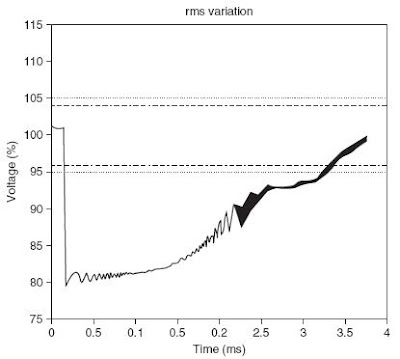
Voltage Sag or Voltage Dip (IEC term) is defined by the IEEE 1159 as the decrease in the RMS voltage level to 10% - 90% (1% - 90% for EN 50160) of nominal, at the power frequency for durations of ½ cycle to one (1) minute. Also, voltage sag is classified as a short duration voltage variation phenomena, which is one of the general categories of power quality problems

Voltage sag (dip) durations are subdivided into three categories: instantaneous (½ cycle to 30 cycles), momentary (30 cycles to 3 seconds), and temporary (3 seconds to 1 minute). These durations are intended to correlate with typical protective device operation times as well as duration divisions recommended by international technical organizations. Sags are widely recognized as among the most common and important aspects of power quality problems affecting commercial and industrial customers - they are virtually unnoticeable by observing lighting blinks but many industrial processes would have shutdown. Possible effects of voltage sags would be system shutdown or reduce efficiency and life span of electrical equipment, specifically motors. Therefore, such disturbances are particularly problematic for industry where the malfunction of a device may result in huge financial losses.
Voltage Sag Waveform
Voltage Sag (Dip)
Voltage Sag (Dip) Terminology Usage

The term voltage sag has been used in the power quality community for many years to describe a specific type of power quality disturbance - a short duration voltage decrease. The IEC definition for this phenomenon is voltage dip. The two terms are considered to be interchangeable. Generally, sag is preferred in the US and dip is common in European countries.

Terminology used to describe the magnitude of voltage sag is often confusing. According to IEEE 1159-1995, the recommended usage is “a sag to 65%”, which means that the line voltage is reduced down to 65% of the normal value, not reduced by 65%. Using the preposition “of” (as in “a sag of 65%”, or implied in “a 65% sag”) is deprecated. This preference is consistent with IEC practice, and with most disturbance analyzers that also report remaining voltage. Just as an unspecified voltage designation is accepted to mean line-to-line potential, so an unspecified sag magnitude will refer to the remaining voltage. Where possible, the nominal or base voltage and the remaining voltage should be specified.
Voltage Sag to 65%
Sample Voltage Sag to 65% 
Common Causes of Voltage Sags or Dips

Voltage sags are generally caused by weather and utility equipment problems, which normally lead to system faults on the transmission or distribution system. For example, a fault on a parallel feeder circuit will result in a voltage drop at the substation bus that affects all of the other feeders until the fault is cleared. The same concept would apply for a fault somewhere on the transmission system. Most of the faults on the utility transmission and distribution system are single-line-to-ground (SLG) faults.

Voltage sags can also be caused by the switching of heavy loads or the starting of large motors. To illustrate, an induction motor can draw six to ten times of its full load current during starting. If the current magnitude is relatively larger than the available fault current at that point in the system, the voltage sag can become significant.
Typical Voltage Sag Caused By Motor Starting
Voltage Sag Caused By Motor Starting
In addition, voltage sags can affect large areas, particularly if the fault occurs upstream. Events usually start on the transmission or distribution system - faults and switching.
Voltage Sag Area Coverage Is Large
Voltage Sag Area Coverage


Voltage Sag or Dip Protection
Approaches For Voltage Sag Ride-Through
Voltage sags or dips can be alleviated by cooperation of the utility, end-user and the equipment manufacturer in order to reduce the number and severity of its effects and to reduce the sensitivity of equipment to such problem.

1.    Incorporate voltage sag ride-through capability into the equipment. This is generally the less costly and best solution. Tips on ensuring voltage sag ride-through are as follows:

Ø    Equipment manufacturers should have voltage sag ride-through capability curves available to their customers, who should begin to demand these types of curves to be made available so that they can properly evaluate the equipment.

Ø     The company procuring new equipment should establish a procedure that rates the importance of the equipment. If the equipment is critical in nature, the company must make sure that adequate ride-through capability is included when the equipment is purchased.

Ø   Equipment should at least be able to ride through voltage sags with a minimum voltage of 70 percent (ITIC curve). A more ideal ride-through capability for short-duration voltage sags would be 50 percent, as specified by the semiconductor industry in SEMI F-47.

2.    Apply an uninterruptible power supply (UPS) system or some other type of power conditioning to the machine control. This is applicable when the machines themselves can withstand the sag or interruption, but the controls would automatically shut them down.

3.    Backup power supply with the capability to support the load for a brief period.

4.    Utility power system improvements to significantly reduce the number of sags and interruptions (e.g. replacement of relays).

Synopsis:

Magnitude: 0.1 to 0.9 pu 
Source: Utility or large load start by end-users
Duration: ½ cycle to 1 minute
Symptoms: Malfunction or Shutdown
Occurrence: Average of 50 events/year in the US

References:
Bollen, M. (2000). Understanding Power Quality Problems: Voltage Sags and Interruptions.
Dugan, R., McGranaghan, M., Santoso, S., and Beaty, H.W. (2004). Electrical Power Systems Quality (2nd ed.). New York: McGraw-Hill.
IEEE 1159-1995. Recommended Practice For Monitoring Electric Power Quality.
Leng, O.S. (2001). Simulating Power Quality Problems

AUTOMATIC VOLTAGE REGULATORS (AVR) FOR PROTECTION FROM UNDESIRABLE VOLTAGE VARIATIONS

Wednesday, March 23, 2011

Automatic Voltage Regulator (AVR) is a device that is basically intended to improve the voltage regulation of an electrical system – adjust, control or maintain a constant voltage level through the use of either an electromechanical mechanism or electronic components (active or passive). Automatic Voltage Regulators are important since sensitive loads have stringent voltage limits to operate properly and such loads are generally efficient when supplied with voltage near their rated voltage. Accordingly, AVRs protect electrical and electronic devices from the possible damage due to overvoltage and undervoltage conditions. Downtime and equipment damage caused by poor voltage regulation could in turn result to financial costs that would have been avoided by using AVRs.

Automatic Voltage Regulator
Automatic Voltage Regulators come in different sizes and designs depending on its application. For example, in electronics the voltage regulators are small (mounted on printed circuit boards) and usually have a DC output. Meanwhile, distribution utilities use large voltage regulators (up to the size of a small house) to maintain a constant AC voltage. This post will discuss more on the basic operation of AC Automatic Voltage Regulators.

Common types of AVRs for steady-state applications are:


Step-Voltage Regulator
Utility Step-Voltage Regulator

Basic AVR Operation Process

An automatic voltage regulator basically functions almost the same regardless of type and size. It takes in a range of voltage levels and automatically outputs a voltage with a much narrower range of voltage levels. A voltage regulator may have a symmetrical input voltage range (e.g. ±10% of nominal) or an asymmetrical input voltage range. The choice of symmetrical versus asymmetrical input voltage range is dictated by purpose and design of the voltage regulator. To illustrate, a typical AVR for power quality application may have an input voltage range of +10% to -25% of the nominal input voltage and convert this to a regulated voltage range of ±3% of the nominal output voltage. The output voltage regulation range is almost universally symmetrical (e.g. ±3% of nominal output voltage).

Moreover, some AVRs may also perform a voltage step up or step down by converting incoming voltage to a new voltage level of output (i.e. a step up from a 120 V input to a 240 V output) and have the input and output voltage ranges applied to the input and output voltages, respectively. For example, an input voltage of 120 V (variation of +10% to -25%) to an output voltage of 240 V (±3% regulation).

(Next posts about AVR will describe each of the common types of voltage regulators including applications and sizing)

For sample DC voltage regulator projects (click here)

References:

Clark, J. (1990). AC Power Conditioners Design and Application
Dugan, R., McGranaghan, M., Santoso, S. and Beaty, H.W. (2004). Electrical Power Systems Quality (2nd ed.). New York: McGraw-Hill.
Utility Systems Technologies, Inc. (2009). AC Automatic Voltage Regulators

POWER QUALITY BASICS: UNDERVOLTAGE

Monday, March 21, 2011

Undervoltage is classified as a Long-duration Voltage Variation phenomena, which is one of the general classification of power quality problems mentioned in the second post of the Power Quality Basics series of this site. Long-duration voltage variation is commonly defined as the root-mean-square (RMS) value deviations at power frequencies for longer than one (1) minute. It is important to note the duration of one minute or more as this differentiates undervoltage from short-duration voltage variations such as voltage sags.
Undervoltage Waveform
Undervoltage is described by IEEE 1159 as the decrease in the AC voltage (RMS), typically to 80% - 90% of nominal, at the power frequency for a period of time greater than 1 minute. Undervoltage generally results from low distribution voltage because of heavily loaded circuits that lead to considerable voltage drop, switching on a large load or group of loads, or a capacitor bank switching off. 
voltage drop in utility lines

Undervoltage can expose electrical devices to problems such as overheating, malfunction, premature failure and shut down, especially for motors (i.e. refrigerators, dryers and air conditioners). Common symptoms of undervoltage include: motors run hotter than normal and fail prematurely, dim incandescent lighting and batteries fail to recharge properly.

In connection, IEEE discourages the use of the term “brownout” and should be avoided in future power quality activities to prevent confusion. Brownout is sometimes used to describe sustained periods of low power frequency voltage initiated as a specific utility dispatch strategy to reduce delivered power. Basically, the disturbance described by brownout has the same meaning as that of undervoltage. However, there is no formal definition for brownout and it is not as clear as the term undervoltage.

Undervoltage problems may be alleviated by:

1.      Reducing the system impedance - increase the size of the transformer, reduce the line length, add series capacitors or increase the size of line conductors.
2.   Improving the voltage profile - adjust transformers to the correct tap setting (for manual tap changers) or install voltage regulators or automatic on-load tap changers. Voltage regulators include the mechanical tap changing voltage regulators, electronic tap switching voltage regulators and the ferroresonant transformers.
3.    Reducing the line current – de-load the feeder or circuit by transferring some loads to other substations or load centers, add shunt capacitors or static VAR compensators, or upgrade the line to the next voltage level.

The choice of appropriate solution shall be based on the effectiveness of the mitigating device considering its benefit-cost factor.

Synopsis:
Magnitude: 0.8 to 0.9 pu (typical)
Source: Utility or facility
Duration: More than 1 minute
Symptoms: Malfunction or premature equipment failure and overheating of motors
Occurrence: Medium to high
References:
Dugan, R., McGranaghan, M., Santoso, S., and Beaty, H.W. (2004). Electrical Power Systems Quality (2nd ed.). 
IEEE 1159-1995. Recommended Practice For Monitoring Electric Power Quality.
Leng, O.S. (2001). Simulating Power Quality Problems.
Utility Systems Technologies, Inc. (2009). Power Quality Basics

POWER CONDITIONERS FOR POWER QUALITY DISTURBANCE PROTECTION

Sunday, March 20, 2011

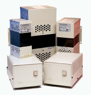
Power Conditioners (also called Line Conditioners or Power Line Conditioners) are devices that can mitigate power quality problems like voltage variations, voltage unbalance, line noise, harmonics, resonance and other power quality disturbances that could cost companies and even residences large amount of opportunity and damage expenses. It function to regulate, filter and/or suppress noise in AC power for electronic equipment and sensitive computers. Currently, there is no official definition for a power conditioner, power line conditioner or line conditioner, but generally it refers to a device that acts in one or more ways to deliver a voltage of the proper characteristics to enable load equipment to function properly.
Power Conditioners
Power Conditioners
Power conditioners could provide voltage regulation while others can correct a variety of other power quality problems. It is also common to find audio power conditioners that only include an electronic filter and a surge protector with no voltage regulating capability. However, as of now, no single power conditioner can correct ALL power quality problems.

Comparison of Power Conditioners
Comparison of Power Conditioners and Their Applications

Basic Specifications For Power Conditioners

Important specifications to consider when searching for power conditioners include:

Ø  Power Rating - this is usually expressed in volt-amps, which is the product of the maximum RMS voltage and the RMS current that the conditioner can handle.
Ø   Input Voltage - the nominal line voltage to which the conditioner is connected.
Ø   Output Voltage – the regulated or conditioned voltage.
Ø   Voltage Regulation Accuracy - the accuracy with which the output voltage is controlled.
Ø  Phase - General public or standard commercial voltages are typically single phase (e.g. computers, office equipment and laboratory instruments). Three-phase power is typically reserved for industrial use for machines that benefit from its efficiency (e.g. industrial motors).
Ø   Frequency - common choices include 50 Hz, 60Hz and 400 Hz. 


Considerations For Power Conditioner Selection

1.   Source Compatibility
Power conditioning equipment must be compatible with the intended power source to ensure its own operation and to avoid interfering with the operation of other loads connected to the same power source. Along with the obvious considerations (input voltage levels, number of phases, and frequency), it is also important to focus on the following subtle ones such as tolerance to sags, swells and surges, limited in-rush currents to prevent voltage sags, limited harmonic input current distortion and limited notching. If taken for granted, the power line conditioner may cause disturbances to other loads. For example, the rectifier of a static Uninterruptible Power Supply (UPS) may produce voltage notches that can cause sensitive loads to malfunction, despite the fact that it provides interruption protection for its load.

2.   Load compatibility
A power line conditioner must be compatible with the sensitive load. To ensure this, load's requirements must be known so that you can match them to a power conditioner with compatible output performance. As an example, if the load's allowable input voltage range is ±5% of nominal, then you don't need a precision voltage regulator to maintain output voltage to within ±1%.
Other considerations to take into account are size of the power conditioner and the basic specifications mentioned above. For instance, in sizing, it is important to account for large variations, as well as the waveform distortion of the load current. This is to avoid excessive output voltage variation and the heating effects.

3.   Applicability
Each power conditioner can be expected to protect against specific power quality problems. However, to get the best protection performance from each device, it is necessary to understand its respective application factors. Thus, it is essential to know the kind of power quality disturbance present in the area in order to determine whether the need is to regulate, suppress and/or filter the incoming power. Subsequently, the decision of what power line conditioner to use will be based on the required correction.

Additional Power Conditioner Features

The following additional features common to power conditioners


Ø  Medical Rating - Power line conditioners with medical ratings are designed and rated for medical or dental use - may include hospital grade ratings.
Ø Frequency Conversion - Line conditioners with frequency conversion include power conditioners that also convert input frequency to a different value (e.g. 60 Hz to 50 Hz converters).
Ø  Bypass Switch - Bypass switches for taking power conditioners off-line without physically removing them; allows unconditioned power to pass through.
Ø  Indicators or Readout - Readouts or indicators include visual display indicating status or performance; may include simple LED indicators or more elaborate readouts.


References:
Baggini, A. (2008). Handbook of Power Quality. UK: Wiley
Clark, J. (1990). AC Power Conditioners Design and Application
EPRI Solutions. (2005). Applying Power Conditioning Equipment
Utility Systems Technologies, Inc. (2009). Power Quality Basics

UNDERVOLTAGE CASE STUDY: LONG DISTRIBUTION FEEDER PART 2

Friday, March 18, 2011


Alternatives

The following are the general solutions to mitigate undervoltage problems as discussed in this site (Please refer to Power Quality Basics):

1.  Reduce the system impedance - increase the size of the transformer, reduce the line length, add series capacitors or increase the size of line conductors.
2.   Improve the voltage profile - adjust transformers to the correct tap setting (for manual tap changers) or install voltage regulators or automatic on-load tap changers.
3.   Reduce the line current – deload the feeder or circuit by transferring some loads to other substations or load centers, add shunt capacitors or static VAR compensators, or upgrade the line to the next voltage level.

The specific alternatives for this case are:


  1. Adjust substation tap setting to compensate voltage drop within upper voltage limit of Table 1.
Advantages:
Quick, easy and cheap to implement.
Disadvantages:
Major concern for this option is when the tap setting is adjusted, how high would the bus voltage become. Exceeding the upper voltage limit would make this alternative impractical.

  1. De-load feeder by transferring some loads to adjacent feeders, if available.
Advantages:
Quick, easy and cheap to implement.
Disadvantages:
The absence of adjacent feeder would make this option unrealizable. Also, this would require about half an hour of interruption losing energy sales for the duration of the transfer. However, if paralleling is practiced, then, interruption can be avoided.

  1. Install capacitor banks to serve as voltage support while maintaining power factor close to unity as much as possible.
Advantages:
Aside from voltage support, this would reduce line technical losses and can be implemented without feeder interruption.
Disadvantages:
This would require expenses for the capacitor installation.

  1. Install automatic voltage regulators (medium voltage) along the feeder.
Advantages:
Properly regulated voltage.
Disadvantages:
Cost is relatively high compared to capacitor banks.

  1. Upgrade size of feeder conductor
Advantages:
Lessens voltage drop and losses
Disadvantages:
Costly

  1. Put up new substation near the factory
Advantages:
Lessens voltage drop and losses
Disadvantages:
Costly


Recommendations

The root cause of the problem was found out to be that the voltage drop along the utility’s distribution feeder is significant enough to cause an undervoltage condition at the location of the industrial customer. To quickly address the undervoltage problem, it is recommended to implement the following economical alternatives:

1.   Deload feeder by transferring some loads to adjacent feeders, if available.
2.   Install capacitor banks to serve as voltage support while maintaining power factor close to unity as much as possible.


The recommended actions are expected to improve the factory’s receiving voltage to desired levels at the least cost. In this case, a load flow study through software simulation (i.e. ETAP) would come in handy to verify whether implementing the propose solutions are able to correct the voltage. Then, a cost analysis would approximate the expenditure of the chosen projects as compared to the other options.

Figure 5. Factory Voltage Profile After Improvement

Minimum Voltage: 21.8 kV
Maximum Voltage: 23.4 kV

Figure 5 illustrates that after the recommendations were implemented, the voltage at the industrial customer's location improved and are now within the limits set by the utility.

PQWorld

free counters

About Me

My photo
I am a Professional Electrical Engineer with a Masters Degree in Business Administration. My interest is in Power Quality, Diagnostic Testing and Protective Relaying. I have been working in an electric distribution utility for more than a decade. I handle PQ studies, power system analysis, diagnostic testing, protective relaying and capital budgeting for company projects.