Step-Voltage Regulators applied in the utility’s distribution systems are generally medium-voltage mechanical automatic voltage regulators (AVR). It should be noted that there are two distinct types of AC automatic voltage regulators: Medium-voltage (mechanical) and the Low-voltage regulators (mechanical or electronic). The difference in their operation and design clearly demonstrate that their applications are not the same. The latter is intended to protect end-user devices from overvoltage and undervoltage conditions . Nonetheless, this post will focus on the medium-voltage regulators, which is primarily used by the electric utility to compensate for the voltage drop in the feeders or distribution systems. In addition, the term step-voltage regulator is often used to refer to utility AVR.
Step-Voltage Regulator Basic Operation
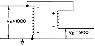
The step-voltage regulator is basically a transformer that has its high-voltage winding (shunt) and low-voltage winding (series) connected to either aid or oppose their respective voltages. Subsequently, the output voltage could be the sum or difference between the winding voltages. For example, if the transformer has a turns ratio of 10:1 with 1000 V applied in the primary, then, the secondary voltage will be 100 V. Adding or subtracting by using the connection mentioned above - the output voltage would be 1100 V or 900 V, respectively. Thus, the transformer becomes an autotransformer with the capability to boost (raise/step-up) or buck (lower/step-down) the system voltage by 10%.
Step-up Autotransformer (Boost)
|
Step-down Autotransformer (Buck)
|
In other words, by switching the location of the physical connection from the shunt to the series winding (reversing switch) and with the turns ratio made variable through automatic tap-changing - the system voltage is adjusted to the required level. This is made possible since the automatic voltage regulator includes microprocessor-based and/or mechanical controls that tell the unit when and how to change taps. Moreover, modern controllers are equipped with data acquisition and communication capabilities for remote applications.
Step Voltage Regulator Schematic Diagram
|
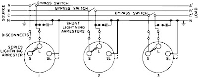
Utility step-voltage regulators usually allow a maximum voltage regulation range of ±10% of the incoming line voltage in 32 steps of 5/8% or 0.625%. That makes 16 steps each for buck and boost – 5/8% x 16 steps = 10%. Utility AVRs can be installed out on the feeders or at the substation bus. The voltage regulator units could either be single-phase or three-phase. However, on a three-phase feeder, it is more common in utility applications to use single-phase units connected in banks of three (e.g. wye-grounded, closed delta). This is because utility distribution lines are typically unbalanced in their construction, added with single-phase loads that create significant unbalance in the line currents. Thus, three independently controlled regulators may very well yield better balance between the phase voltages than a single three-phase unit or ganged operation. Also, there are many installations of open-delta regulator banks on lightly loaded three-phase feeders, which require only two regulators and are less costly than a full three-phase bank.
Voltage Regulator Applications
Step-voltage regulators are typically installed on the following:
Ø Existing feeders - before the point where the voltage drop problem starts with heavy load
Ø Important laterals
Ø To serve a remotely located load
Voltage regulators in the utility distribution systems are relatively slow. These AVRs have a time delay of at least 15 seconds. Therefore, it is not suitable to applications where voltages may vary in cycles or seconds. Utility step-voltage regulators are primarily use for boosting voltage on long feeders where the load is changing slowly over several minutes or hours. The voltage band typically ranges from 1.5 to 3.0 V on a 120-volt base. The control can be set to maintain voltage at some point down the line from the feeder by using the line drop compensator capability. This results in a more level average voltage response and helps prevent overvoltages on customers near the regulator.
Voltage Regulator Sizing and Connection
These are the basic steps in determining the size and connection type of the voltage regulator for utility applications:
1. Determine the system configuration (i.e. 3-phase, 4-wire multigrounded wye or 3-phase, 3-wire delta). This will be the basis for AVR connection type.
2. Establish the amount of voltage regulation needed (e.g. ±5%, ±10%)
3. Determine the system phase voltage on which the AVRs will be connected. Remember that the phase voltage is affected by the system configuration (1).
4. Calculate the maximum load current of the feeder or line.
5. Multiply the voltage regulation (2), system phase voltage (3) and maximum line current (4) to get the required kVA size of the automatic voltage regulator.
For example, compute for the step-voltage regulator size needed by a 3-phase, 4-wire multigrounded feeder with a system voltage of 13800Y/7970 V. The required voltage regulation is 10% and the peak connected load is 6.0 MVA.
1. System Configuration is 3-phase, 4-wire, multigrounded wye - means that the voltage regulators shall be connected grounded wye.
2. Voltage regulation = 10%
3. Phase voltage is the line-to-neutral voltage = 7.97 kV (since it is a 4-wire multigrounded wye feeder)
4. Load current = 6.0 MVA / (1.732 x 13.8 kV) = 251 A
5. Voltage Regulator kVA Size = 10% x 7.97 kV x 251 A = 200 kVA
Use three 32-step voltage regulators, each with a standard rating of 250 kVA, 7970 V, ±10% regulation.
For a more detailed explanation about step-voltage regulators (Click here)
References:
Cooper Power Systems. (1993). How Step-Voltage Regulators Operate. Pittsburgh: Cooper
Dugan, R., McGranaghan, M., Santoso, S. and Beaty, H.W. (2004). Electrical Power Systems Quality (2nd ed.). New York: McGraw-Hill.


5 comments:
Simple... 3-phase, 4-wire multigrounded wye or 3-phase, 3-wire delta. If it's a wye system the (3) single VRs are in a wye bank, if it is a delta system the (3)single VRs are in delta bank or (2) single VRs are in the open delta configuration.
But what would you do, if your system is 3-phase, 3-wire wye system with HRG neutral. How would you connect your (3) single phase VRs - wye or delta?
I got an expert's advise from Dan Landreman of Cooper Power Systems:
"For a three wire system with a High Resistive ground, it would be best to connect the regulators in a delta configuration."
"The 3 wire HRG system will shift the neutral point of the regulators as the regulators operate. This can cause the three independent regulators to “fight” each other unless special control algorithms are employed. Since three wire systems connect their loads line to line, it is much better to regulate the line to line voltage."
Thanks very much to the poster!! This article really helps me so much to do my project!!!! Millions Thanks!!!
for three wire system , can we connect three single step voltage regulator and let the common point SL ground point , and if this can be done what the preferred protection elements shall implemented in case of ground disconnection
thanks
Thank you guys these information very good and great
Post a Comment