STATCOM
or Static Synchronous Compensator is a shunt device, which uses
force-commutated power electronics (i.e. GTO, IGBT) to control power flow and
improve transient stability on electrical power networks. It is also a member
of the so-called Flexible AC Transmission System (FACTS) devices. The STATCOM
basically performs the same function as the static var compensators but with
some advantages.
The
term Static Synchronous Compensator is derived from its capabilities and
operating principle, which are similar to those of rotating synchronous
compensators (i.e. generators), but with relatively faster operation.
STATCOMs
are typically applied in long distance transmission systems, power substations
and heavy industries where voltage stability is the primary concern.
In
addition, static synchronous compensators are installed in select points in the
power system to perform the following:
- Voltage support and control
- Voltage fluctuation and flicker mitigation
- Unsymmetrical load balancing
- Power factor correction
- Active harmonics cancellation
- Improve transient stability of the power system
Design
A
STATCOM is composed of the following components:
A. Voltage-Source
Converter (VSC)
The
voltage-source converter transforms the DC input voltage to an AC output
voltage. Two of the most common VSC types are described below.
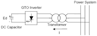
1. Square-wave
Inverters using Gate Turn-Off Thyristors
Generally,
four three-level inverters are utilized to make a 48-step voltage waveform. Subsequently,
it controls reactive power flow by changing the DC capacitor input voltage,
simply because the fundamental component of the converter output voltage is
proportional to the DC voltage.
In
addition, special interconnection transformers are employed to neutralize
harmonics contained in the square waves produced by individual inverters.
 |
| GTO-based STATCOM Simple Diagram |
2. PWM
Inverters using Insulated Gate Bipolar Transistors (IGBT)
It uses
Pulse-Width Modulation (PWM) technique to create a sinusoidal waveform from a
DC voltage source with a typical chopping frequency of a few kHz. In contrast
to the GTO-based type, the IGBT-based VSC utilizes a fixed DC voltage and
varies its output AC voltage by changing the modulation index of the PWM
modulator.
Moreover,
harmonic voltages are mitigated by installing shunt filters at the AC side of
the VSC.
This
component provides the DC voltage for the inverter.
C. Inductive
Reactance (X)
It
connects the inverter output to the power system. This is usually the leakage
inductance of a coupling transformer.
Mitigate
harmonics and other high frequency components due to the inverters.
STATCOM
Operation
Basic
Principle of Operation
In the
case of two AC sources, which have the same frequency and are connected through
a series reactance, the power flows will be:
- Active or Real Power flows from the leading source
to the lagging source.
- Reactive Power flows from the higher to the lower
voltage magnitude source.
Consequently,
the phase angle difference between the sources decides the active power flow,
while the voltage magnitude difference between the sources determines the
reactive power flow. Based on this principle, a STATCOM can be used to regulate
the reactive power flow by changing the output voltage of the voltage-source
converter with respect to the system voltage.
Modes of
Operation
The
STATCOM can be operated in two different modes:
A.
Voltage Regulation
The
static synchronous compensator regulates voltage at its connection point by
controlling the amount of reactive power that is absorbed from or injected into
the power system through a voltage-source converter.
In
steady-state operation, the voltage V2 generated by the VSC through
the DC capacitor is in phase with the system voltage V1 (δ=0), so
that only reactive power (Q) is flowing (P=0).
1.
When
system voltage is high, the STATCOM will absorb reactive power (inductive
behavior)
2.
When
system voltage is low, the STATCOM will generate and inject reactive power into
the system (capacitive).
Subsequently,
the amount of reactive power flow is given by the equation:
Q =
[V1(V1-V2)] / X
B. Var
Control
In
this mode, the STATCOM reactive power output is kept constant independent of
other system parameter
STATCOM
versus SVC
The
STATCOM has the ability to provide more capacitive reactive power during
faults, or when the system voltage drops abnormally, compared to ordinary
static var compensator. This is because the maximum capacitive reactive power
generated by a STATCOM decreases linearly with system voltage, while that of
the SVC is proportional to the square of the voltage. Also, the STATCOM has a
faster response as it has no time delay associated with thyristor firing.
Nevertheless, these advantages come at a higher price (about 20% more).
Reference:
Hingorani, N. and
Gyugyi, L. (2000). Understanding FACTS; Concepts and Technology of Flexible AC
Transmission Systems.


No comments:
Post a Comment